Learning outcomes
On completion of this chapter you will know:
- The nature of a computer’s memory
- How data is stored in the memory
On completion of this chapter you will know:
To many people computers seem to be all-knowing, almighty machines with superhuman intelligence that can perform such impossible tasks as processing the salaries of 5,000 employees in a matter of seconds, allow us to create documents and printouts that would be impossibly expensive to produce on old fashioned printing machines and create characters and actions in movies such as Lord of the Rings, the Harry Potter series etc., that would be impossible to produce in real life. The most recent movie – Avatar – creates a fantasy world that looks as real as our own and is also in three dimensions. This again is done using computer graphics.
Despite the superhuman wonders that a computer can produce for us, it is surprising that the only action that a computer is capable of doing is addition. It is not even able to subtract. Using a system called 2’s compliment a computer compute can be tricked into subtracting – but it thinks that it is adding. Multiplication is performed by repeated addition and division is again performed by repeated subtraction.
If this is the case, ie, if a computer can only perform addition, then how is it able to perform the wonders that it does so easily? The answer is the speed at which it performs its addition. Some computers can perform more than one billion additions per second! It is with various combinations of mathematical operations done at such incredible speeds that a computer can perform the huge variety of actions it does.
The two most essential parts of a computer are the CPU and the memory. The memory is where the data to be processed is held and the CPU (Central Processing Unit) is where the actual processing takes place. In this chapter we shall look at the computer’s memory, how data is stored there and how that data is accessed. After that we shall examine the CPU.
Go to topA computer is an electronic machine which means that it works with electricity. An electric current can be either on or off. To a computer a current being on in a circuit means 1 while a current being off means 0. For this reason a computer uses binary arithmetic to do its calculations, which is why we paid so much attention to binary and hexadecimal numbers in the chapter Binary Numbers.
A computer stores the data in its memory using circuits that can be turned on or off. These circuits are arranged in groups that are referred to as registers. The smallest register will have eight circuits in it. These circuits are called bits. Eight bits is referred to as a byte. The memory can be visualized as below, which shows a bank of nine registers each containing eight bits.
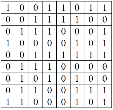
Here in Figure 2‑1 we have 1’s and 0’s in the different bits of the registers but in reality they would simply be circuits that would be turned on or off. The computer, however, can interpret the on/off of the switches as 1 or 0. In the above example the top three registers contain the binary equivalents for 155, 60 and 113.
A computer’s memory is made up of banks of registers like the above. The more of those registers that a computer has, the larger is its memory. Thus a computer with 1024 registers is said to have one Kilobyte (1K) of memory. (1024 = 210). Other sizes of memory are
Thus when we say that a computer has 100Mb of memory we are saying that it has 100 x 1,048,576 = 104,857,600 bytes of memory. Similarly if we are told that a hard disk has a capacity of 30Gb, it means that it can hold 30 X 1,073,741,824 = 32,212,254,720 bytes.
Go to topThe largest number that can be stored in an 8-bit register (1 byte) is the binary number 111111112, which is 255 base ten. This of course is not a very large number, and in order to represent larger numbers they are spread over more than one register. In some applications an integer is defined as taking up two bytes. Thus the largest value that can be stored here is the binary number 11111111 which is 65,536 base 10. Again for many applications this is not big enough and there is a data type called Long Integer which is stored over four bytes. The largest value that this type can hold is 4,294,967,296.
Go to topWhen writing we denote negative numbers by putting a minus sign in front of them. Positive numbers are denoted by the plus sign in front of them, but the absence of any sign implies that it is a positive number. How do we denote negative numbers in the registers of a computer? After all we cannot put a minus sign in front of them. The way to do it is to use the leftmost bit or commonly known as the most significant bit to denote the sign. Here we shall look at only If this bit has a zero value then the number stored is a positive number, whereas a 1 in the most significant bit indicates that the number is a negative one. Thus the largest positive number that can be stored in this manner is the binary number 01111111 is 127. The smallest negative number that can be stored is the 2’s compliment of 128.
Go to top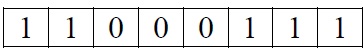
A number can be stored in a computer’s register as either signed or unsigned. In the example above if we are told that the register contains an unsigned number then the contents can be interpreted as
110001112 which evaluates to 199 base ten.
On the other hand if the number is said to be a signed integer, then the 1 in the most significant bit indicates that it is a negative number and thus the 2’s compliment of the rest of the register has to be calculated.
Go to topFrom what we have discussed above we see that only numbers in binary form can be stored in the computer’s memory. There appears to be no facilities for storing text. Yet most people’s introduction to computers is through word processing and here we see that computers can process text very well indeed. So then how does it know what the letter A is? Or the letter B? Or the letters C, D, E etc?
The answer is that alphabetical characters as well as punctuation symbols are coded as numbers. An example is the character A would be represented by the number 65, B by 66 etc. There are many systems for coding alphabetical characters – the two most common ones are the EBCDIC code and the ASCII code. The ASCII (American Standard Code for Information Interchange) code is the most common and the one we shall use here. Below is shown some of the code.
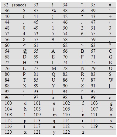
Here we notice that 65 is the code for A, 66 for B etc. this continues in sequence up to 90 which is the code for Z. We would expect that the lower case letters: a, b, c etc. would begin immediately after the upper case ones, but in fact they start at 97. Why is this?
Remember that the binary equivalent of 65 is 01000001 while the binary code for 97 is 01100001. In binary the only difference between those two numbers is the third bit from the left. If this bit is zero then the letter is a capital one while if it is one the letter is lower case. Thus to change a letter from upper to lower case or vice versa we simply change the third bit from the left..
We might expect that the numeric characters: 1, 2, 3, etc would at least have their equivalent in the ASCII code, i.e. that the code for the character 1 would be 1 etc. but this is not the case. The ASCII code for the character zero is 48, for 1 is 49 etc. up as far as 57 for 9.
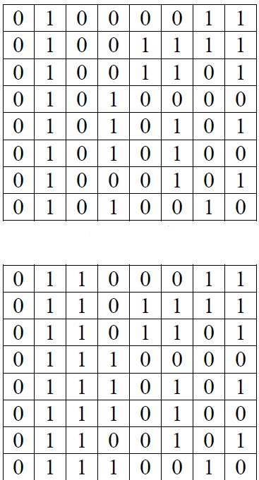
Figure 2‑2 below show what the registers of a computer would look like if the word COMPUTER was written there in capitals and Figure 2‑3 show what the same registers would look like if it was written in lower case. Notice that the contents of both figures are the same apart from the third column from the left..
 Go to top
In the first register of Figure 2‑2 the value C is not stored. What’s stored instead is the binary version of the number 67. If we are examining the memory register by register how do we know whether the first register contains the integer 67 or the ASCII version of the letter C.? The answer is that, by looking at the actual register, we have no way of knowing how to interpret the data in the register. What this data actually means, depends on the programme that is reading the data. Thus if it is a programme that is told to read the value in the first register and add 16 to it then that programme will interpret the register’s contents as the binary version of 67, and then add 16 to it. On the other hand if a wordprocessor reads the same register, it will simply look up the ASCII table and if printing the data to the screen print the letter C instead of 67. If the contents is interpreted as the letter C then adding 16 to it would either be meaningless or else would give the letter S, which is 16 characters further on from C.
Go to topThe most basic data type for a computer is the bit. This corresponds to one single switch in a register and can have values of on and off, signifying 1 or 0. On its own its use is limited either switching on appliances or checking that they are switched on. For numeric calculation we have to combine a number of bits together.
The smallest number of bits that are combined together is eight. A collection of 8 bits is called a byte. As stated earlier the largest number that can be stored in a byte is 255 which is equivalent to 111111112. although a standard unit of data, it is itself too small form most practical mathematical applications.
An integer is made up from 2 bytes or in other words 16 bits. If using an unsigned integer the largest value that can be stored is the binary equivalent of 11111111111111112, which is 65,535. Using signed integers, i.e. where the most significant bit represents the sign of the number, the range of values that can be stored in it is -32,768 to +32,767.
The only difference between Long Integers and normal Integers is that the latter use 4 bytes or 32 bits. Its signed version ranges from -2,147,483,648 to 2,147,483,647.
In normal mathematics if we have a very long number such as 231453784100000000000, we usually write them as 2.3145378 X 10²⁰ or 2.3145378E20. In this case the 20 is referred to as the exponent and 2.3145378 as the mantissa.
We use a similar technique to represent decimals in the computer. We shall start with a simple example using only 1 byte. If we take the value 01111001 we can break it up as follows: let the first 4 digits be the mantissa and the next four digits be the exponent. The first four digits, 0111 converts to 7 or 7.0 while the next four 1001 convert to 9. Thus the contents of the register can be represented as 7 X 910. This is equivalent to 24,407,490,807. This indicates that even in a single byte we can code very large numbers by using one part of the register as the exponent and the other part as the mantissa.
In Figure 2‑2 and Figure 2‑3 we have examined the contents of nine memory registers regarding how data is stored in them. We must now look at how the data is actually put into those registers. To keep the explanation simple we shall look at an extremely small computer with only nine registers as shown below in Figure 2‑4
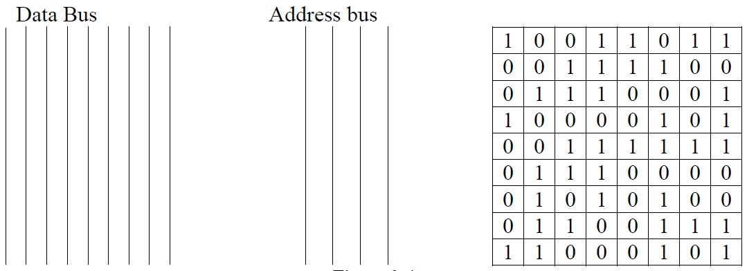
Alongside the registers we have two buses, the data bus and the address bus. The registers themselves are numbered 0, 1, 2, 3, 4, 5, 6, 7 and 8 or in binary terms: 0, 1, 10, 11, 100, 101, 110, 111, 1000. If the processor wants to select a particular register it puts the address of that register on the Address Bus. Thus to select the first register – i.e. register 0 then zero is put on the address bus. This is done by turning each line of the bus off. Once this is done the first register is selected. Once the register is selected the contents of that register is put on the data bus. If the second register – register 1 - was to be selected then the value 1 would be put on the address bus i.e. the rightmost line would be on and the other three would be off. With this combination the second register would be selected and its contents could be read. If the eighth register – register 7 - was to be read then 111 would be put on the address bus or the three rightmost lines would be live and the leftmost would be off. Similarly if the ninth register – register 8 – was to be read then the leftmost line would be live and the other three would be off.
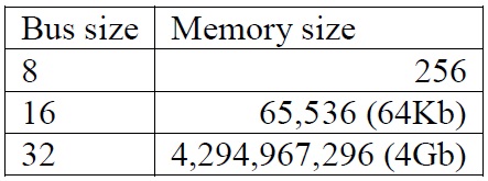
From this we can see that using a four bit address bus we can access registers in the range 0 – 11112 or 0 – 15. Thus a 4-bit address bus would allow us to access 16 registers. Any registers beyond this could not be accessed. Thus the size of the address bus determines the size of the memory with the general rule that an address bus of x lines will allow a maximum memory of 2x. The table below shows some actual values.
 Go to top
The memory is where all data processing occurs. When we type text into a word processor that text is stored in the memory. When we bold, underline or change the font of a piece of text we are altering the contents of the memory area where that piece of text is stored.
In order for this to happen two things reside in memory at the same time, although in different parts of it:a programme and the data it is to process. Examples of programmes are Microsoft Word and Microsoft Excel. Below in Listing 2‑1 is another example of a programme
This listing is a very small programme of 13 lines that calculates a very simple payroll application. Let us examine it. Firstly notice that, even though you may be unfamiliar with programming that there are quite a large number of English words in the listing above and in fact bear no relation at all to the binary codes that we have seen in Figure 2‑1, Figure 2‑2 and Figure 2‑3. The reason for this is that the code in Listing 2‑1 is written in what is called a high level language, Visual Basic in this case. High level languages are designed to be easily read by humans but are completely unreadable to a computer. For this reason they have to be translated into binary code so that the computer can understand them. In reality it is the binary code that actually runs and not the Visual Basic code in Listing 2‑1.
This binary code, however, is very complex and in order to examine the programme-data relationship in memory we shall be referring to the Visual Basic code in Listing 2‑1. Bear in mind however that it is its binary code translation that will actually run.
Running a programme means first placing its code into the computer’s memory and then executing its instructions line by line. In Listing 2‑1 the first five instructions, i.e. lines 2 – 6, make extra space in the computer’s memory for the data that is to be processed. Line 2 – Dim hours as Integer – is telling the system to reserve two bytes of memory and to call that two-byte area hours. Lines 3 – 6 reserve similar areas for other integers. Thus our programme requires ten bytes of memory for its data.
Once the area in memory has been reserved the programme now starts to use that area for processing data. At line 7 the value 40 (in reality its binary equivalent) is stored in the area called hours. Line 8 performs a similar operation with the area rate and the value 8. Line 9 is equivalent to saying multiply the value stored in the area called hours by the value stored in the area called rate and store the result in the area called gross. Lines 10 and 11 work in a similar fashion. Finally line 12 displays the values stored in the areas called hours, rate, gross, tax and nett on the computer’s screen.
From the above exercise we see that a programme is a series of instructions to the computer to the computer on how to perform a particular task. We also see that this programme is stored in the computer’s memory. The first action of the programme is to reserve space in a different part of memory to store the data that the programme needs. Once the data area has been reserved the programme now starts a series of steps for processing that data.
Programmes like Word and Excel work in exactly the same way as the small programme we examined above. Those programmes will also reserve a block of memory in which to store the text that will be processed on Word or the numeric data that will be processed in Excel. When we create a new file in either of those two programmes and key data into it, we are simply filling in the area reserved by the programme for its data. Similarly when we open an existing Word or Excel file we are simply filling the memory area reserved by the programme with the data that was stored on a disk file.
Go to top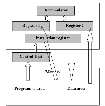
Figure 2‑5 is a simplified diagram of a generic Central processing unit. In the lower part the memory is divided into two areas: programme area and data area. The CPU is in fact made up of the Control unit and the Arithmetic and Logic unit. The ALU consists of the Accumulator, two data registers and the Instruction register. A real CPU contains far more circuitry but for the sake of simplicity they have been omitted.
The ALU itself is only capable of only adding numbers. It performs subtraction through the 2’s compliment method that we have examined in chapter1. Multiplication is performed through repeated addition. Thus 4 X 5 would be calculated as 4 + 4 + 4 + 4 + 4. Division is performed through repeated subtraction. Logical operations such as >, < or = are performed through subtractions and testing if the result is positive, zero or negative.
Now let us look at how the CPU processes simple instructions. As an example supposing we have to do a calculation such as total = cost + GST. Remember that the computer does not understand words such as cost, total etc. For the computer to be able to understand the above calculation the value of the cost would have to be stored in a register in the data area of the memory. Let us say that it is stored in register 00001111. Again let use say that the value of the GST is in register 00010000 and that the total will be stored in register 00010001. To perform the calculation we would need simple instructions as follows:
Once again the above instructions are in English and COMPUTERS DON’T UNDERSTAND ENGLISH! For this reason we will have a set of binary codes as follows:
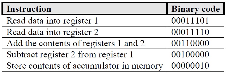
Using the codes in Table 2‑1 we can get a closer approximations to how the programme in memory would look. If 00011101 means Read data into register 1 then 00011101 00001111 will mean Read the contents of register 00001111 into register 1.
Similarly 00011110 00010000 will mean read the contents of register 00010000 into register 2.
Table 2‑2 below shows us more clearly what our programme would look like. The binary code for the programme would be stored as in the first column of the table. The second column is there only to explain to the reader what the data in the registers is about.
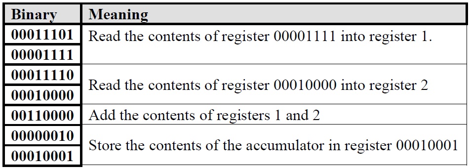
Running the above code would involve the following steps:
Computers are machines that work on electrical power. An electric circuit can be either on or off. This is interpreted by the computer as 1 or 0. Consequently the computer can perform mathematical operations using only binary numbers.
A computer’s memory is made up of registers. Each register contains eight circuits or bits, each of which can be either on or off. Thus the largest number that an eight bit register can store is 111111112, which is 255.
The registers in a memory are accessed by a bus. The address of the register we want is put on the bus. The bus is made up of parallel lines and the number of lines in the bus determine how large the memory can be.
The memory is simply used to hold data. All of the processing is done by the CPU. Data from memory is transferred to the CPU via the bus. After the CPU has performed the processing the new data is stored back into the memory again using the same bus.
Go to top